
Cam lock installation for a production cabinet starts with the selected model’s assembly drawing. The lock body, panel opening, mounting hardware, stop arrangement, and cam must form one defined configuration. A generic sequence of “drill, insert, and tighten” leaves too many of those decisions unresolved.
This guide is for cabinet and enclosure manufacturers preparing assembly instructions and approving samples. It explains the mounting sequence of a conventional keyed cam lock while separating model-specific instructions from the checks needed to release a repeatable assembly. It is not a lock-removal or entry guide.
Confirm which product the instruction describes
A keyed cabinet cam lock and a furniture cam connector are different products. The former operates a locking cam; the latter joins furniture components. A search result headed “cam lock installation” may concern either one. Identify the manufacturer’s model and the assembly drawing before adopting an instruction.
For the lock, establish the body or housing reference, cam part number and orientation, retention method, and supplied accessories. Do not use the cylinder’s external appearance as the only configuration identifier. Keep the panel drawing and supplier instruction revisions with those references.
A manufacturer’s exploded drawing makes the distinction concrete. Southco’s CM installation material identifies the housing, mounting nut, cam, attachment, and model-dependent accessories. Its installation values belong to those products; they must not be copied into an instruction for a different lock.
Approve the panel opening before assembly starts
Review the panel in its finished condition. The required opening includes its profile and orientation, not only a nominal diameter. Where the selected design uses flats or another anti-rotation feature, that feature must correspond to the housing and drawing.
Check the approved panel-thickness range, mounting surface, reinforcement, and space for the specified retention hardware. Confirm which drawing defines the opening’s limits and how the production process verifies them. Coating and the finished edge condition belong in that review where they affect the specified fit.
Do not enlarge an opening, omit hardware, or introduce an unapproved spacer to make a sample assemble. Record the discrepancy and obtain the responsible engineer’s disposition. An assembly instruction should identify an approved fit, not normalize an undocumented adjustment.
Use the cam lock dimension checklist for the drawing inputs. This installation review begins where those inputs become an actual assembled panel.
Separate housing retention from cam attachment
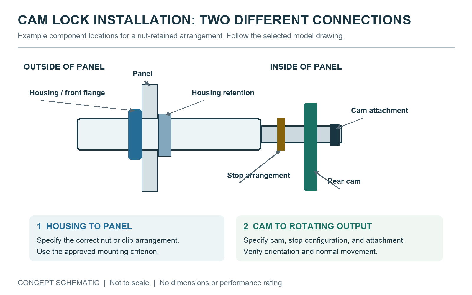
These two connections do different jobs. Housing retention secures the lock body to the panel. Cam attachment connects the rear cam to the rotating output. The mounting nut and the cam fastener should therefore appear as separate items in the instruction and parts list when that is how the selected model is constructed.
For a conventional nut-retained arrangement, the housing is introduced through the prepared opening from the outside and the specified retention hardware is fitted from the inside. A clip-retained arrangement uses its specified clip and groove instead. The correct method is the one documented for the selected model; these descriptions are not interchangeable instructions.
For example, the Artcobell cabinet-door instructions show a particular nut-retained lock followed by its stop washer, cam, and cam screw. They are useful evidence of why the parts must be identified, not authority for applying that sequence to every cam lock.
Where tightening is required, the work instruction must reference the manufacturer’s approved criterion for the exact connection. Do not create a general torque from a different catalog, from the fastener’s appearance, or from the phrase “tighten securely.”
Set the stop and cam orientation from the drawing
If the model uses a separate stop washer or stop component, identify its reference and orientation. Other designs control travel differently. The instruction must show the selected arrangement rather than assuming every lock has the same loose parts.
Mark the viewpoint used for rotation, the normal unlocked position, the normal locked position, and the cam orientation. A straight and an offset cam are different configurations. A drawing that shows only the keyway can leave the rear assembly ambiguous.
Southco’s PT rotation drawing is an example of a document that defines its direction convention and depicts the cam positions. For a production order, obtain the equivalent approved information for the selected lock.
Record key-removal behavior separately from the cam’s end positions. Observing that a key can be removed does not replace checking the intended engagement. For the movement itself, refer to the cam travel and frame-engagement guide.
Verify the installed assembly in its actual surroundings
A lock can move on a bench while its installed cam meets a frame, shelf, cable, or other component differently. Review the complete travel and final engagement in the intended panel and receiving structure. Use the assigned key on an authorized development sample; stop if the review requires force or an unsafe action.
| Check | Evidence to retain | What a discrepancy means |
|---|---|---|
| Housing and mounting arrangement | Sample identity, panel reference, opening orientation, and the specified fixing components. | The installed condition needs comparison with the approved drawing; do not assume a cam change will resolve it. |
| Cam travel and end positions | Rear-view observations for normal unlocked, moving, and locked states. | Identify the observed position or contact point before assigning a cause. |
| Engagement with the receiver | The relevant closed-panel section and observation against its acceptance criteria. | A turning key alone does not establish that the intended closure was achieved. |
| Normal operation and key removal | Required behavior, supplied option reference, and observed result. | Refer an option or operation mismatch to the reviewer; do not modify the mechanism. |
The project must supply its acceptance limits and test methods. This table is an editorial review framework, not a strength test, certification procedure, or WELLHW factory inspection standard.
Turn the approved sample into a usable work instruction
An instruction should show the operator the accepted configuration: the named components, their order and orientation, the specified connections, the approved setting references, and the checks to perform. An annotated photograph of the actual approved sample is more useful than a generic stock image.
Keep the parts list and drawing identifiers visible on the instruction. If a cam, stop, clip, washer, panel revision, or supplier option changes, compare the change against the released assembly. Do not assume that an unchanged cylinder model preserves the whole installation.
Consider a hypothetical change from a nut-retained housing to a proposed clip-retained model. The buyer should request the new mounting details and review the relevant panel condition and assembly method before accepting the substitution. This example identifies the review boundary; it is not an approved interchange.
For a supplier review, send the panel drawing, proposed lock and cam references, current assembly instruction, sample identity, and marked questions through the WELLHW project contact page. Keep missing requirements visible so the discussion can resolve them before production release.
